Tutorials
Fixing the Dreaded “KC-135 Outer Wing Droop”
Dec
When AMT/ERTL designed their KC-135 Stratotanker kit series (the EC-135 kit is a previously unreleased version of this series), they wanted to get the thinnest possible plastic parts. This was their first effort in designing and tooling a model aircraft kit from the ground up. As a result, the wing and fuselage parts are marvelously thin. It was also the largest kit ever tooled by the company in Korea that did the work, so was something of a learning curve for all parties.
This presented a couple of potential problems. One of them is that, over time, the thickness of the plastic on the upper wing, and thus its rigidity, is not sufficient to support the weight of the lower outer wing panel and engine. As a result, over time the outer wing panel will droop, giving the aircraft an odd and inaccurate appearance. In addition, there is a potential mismatch between the levels of the lower outer wing panel and the center section.
Chuck Davenport – Major, USAF (Ret), excellent model builder, and long-time friend – has provided AMtech with the following illustrated instructions on how to fix both the droop and level problem. It is involved, but not difficult. AMtech would like to thank Chuck for his help here, and also with his contribution to the Mission Profiles.
Take it away, Chuck!
“When ERTL released the 1/72 scale KC-135 in the ‘90’s, I wrote an article for the IPMS/USA Journal magazine detailing an alternate procedure for assembling the wings. The company did a wonderful job of tooling the model, but the wings were so beautifully thin that the lower wing joints were weak and difficult to align. In addition, the joint, if assembled according to the instructions, did not support the inboard engine pylon at the proper angle. So that you can get the most out of your EC-135 ARIA/ALOTS model, AMtech has included these notes for ensuring a strong and properly aligned lower wing joint.
Step 1:
Remove the mating ledge from all the lower wing surfaces. I am using a detail-removing tool from Micro-Mark, but a sharp hobby knife will work as well. Remove small sections at a time to prevent cutting into the external wing surface.
Step 2:
Look at the wing parts edge-on and you will see that the thickness of the parts vary. We are going to make sure the exterior surfaces of the wing match up by building up the interior. Cut a strip of .040 plastic card approximately ½” wide to overlap the joint. Clamp it loosely in place. (I have cut two pieces in the photo at left.) The lower wing exterior surfaces will not be level with each other. Begin sliding sections of .010 plastic card under the .040 card until the two lower surfaces are level. Carefully remove the clamp, and glue the plastic card in place. I recommend Ambroid’s Safe-Weld for its extended working time. After about 5 minutes, the bond will be set. Do not get too much glue into the joint to prevent damage to the exterior wing surfaces by the clamps.
Step 3:
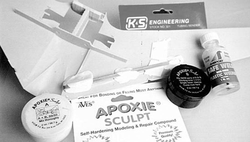
While you are at it, why not reinforce that thin wing for long-term display with a wing spar? Bond a section of K&S 1/8” rectangular brass tube to the lower wing surface with Aves Apoxie Sculpt. Spread a film of Ambroid Safe-Weld on the wing surface to promote a strong molecular bond between the plastic and the Apoxie Sculpt. Press the brass into the putty, which is set back from the leading edge approximately ½”. While the Aves Apoxie Sculpt is curing, temporarily fit the upper wing surface to properly position the brass tube. Once cured and assembled, the spar will prevent the wing from sagging over time.
Step 4:
For those who wish to create the most accurate model, cut a NACA inlet (the triangular type) into the lower right wing/fuselage joint as shown at left. The KC-135A/E/Q/R aircraft, upon which the EC-135 kit is based, needed only one air conditioning inlet and that is the basic fuselage style ERTL tooled for its model. However, the RC-135s and many EC’s featured an additional air inlet on the right side of the aircraft.
Chuck Davenport